Wednesday 30 December 2020

More CADing

 Following on from the last post where I'd drawn up the plenum & the throttle body in CATIA V5, I then refined the design & re-drew it in SolidWorks as I find it more intuitive.

Looking at the compound angle cut in the plenum I realised there was a lot of space on the flat closing plate, which was an ugly feature so I moved the TB as far to one side as I could get it & yes, there was just enough room for the Idle Speed Control Valve.

The way the system works is that the butterfly in the TB shuts off the airflow to the engine, but there is a bypass drilling that allows air past the butterfly into a chamber in the base of the TB. This chamber is connected via a pipe within the Ford inlet manifold to the ISCV which meters air into the engine to allow it to idle at the correct speed. As I'm not using the Ford inlet I needed to duplicate this system.


This is the same view as above but with the TB & the ISCV removed, you can see the 3D printed mounting block with the large hole for the main airway & beneath it the collector chamber for the bypass air. To the right are 2 holes for mounting the ISCV, an upper hole coming from the collector chamber & a lower hole straight into the plenum.


This is the same view again with the mounting block shown transparent & the airway through it highlighted.

Hopefully this should all work wonderfully well. I am a little concerned about the temperature resistance of the 3D printing, but the Ford inlet manifold is thermoplastic & that's in direct contact with the cylinder head, this will be well away, thermally insulated by the silicone hoses & cooled by the airflow, so fingers crossed.


Also currently un-reported in this organ - the engine I bought was missing an upper cam belt cover. On the Fury I made a cover from aluminium to make the engine look older that it was. That's not a consideration on the much more modern looking Quantum, so I drew one up & printed it, for the first time I changed filament colours in mid-print & was quite please with the result.


It's certainly a unique touch.

Monday 28 December 2020

Jommatry


I think I've worked out the correct shape for the plenum to get the throttle body ("TB") to clear the brake servo & point the the air intake somewhere towards the front of the car. This has mostly happened because it's too cold in the garage & I can do CADing in the house. The pic to the right is the plenum with a very roughly modeled TB on the right hand side - the viewpoint is more-or less standing in front of the car looking down over the engine. At the right hand side the plenum has been cut on a compound angle (an angle in two planes) to tip the TB forward & up to clear the brake servo.


If I'd made the cut at two angles, the shape would be difficult to transcribe onto the plenum for cutting, so I used a plane controled by three points to cut the CAD model, each point is a measured distnce along one of the folds, so marking out is easy, draw on the points, roughly align them & join with a pencil line.

This is how it looks on the engine. It's not precise, but there's "wriggle room" by adjusting the length of the legs in the silicone hoses connecting the inlet runners to the plenum. A by-product of fitting the TB here is a nice smooth throttle cable run.


So here's what I mean - there's the cut line marked on the plenum & it's obviously not striaght.


But seen from the other angle, it's a stright cut line! It's like magic isn't it?

When I'm feeling brave (probably after the silicone hoses have arrived & been test fitted) I'll slice down that line, cut some 1/4" plate to fit, tap four holes to match the throttle body & weld it together - OK, I'll get someone else to weld it together.

But if it works that's another major hurdle crossed.


Festive Period

 Over the last few days I've made a little progress, I've fitted the inertia shut-off switch to shut down the fuel pumps in the event of a crash, the switch I got had three terminals, a common, a normally on & a normally off, so I've wired the supply from the relay to the common, wired the normally on to the fuel pumps & the normally off to a lamp adjacent to the switch. The switches don't usually trip, but if it does the light will draw my attention to the reason the engine won't start.

I've also been looking at the inlet plenum - & cutting it up.

I did some trial fitting & found that, as expected, if I fitted it the was the manufacturer intended it hit the suspension turret - it was intedned for a rear wheel drive car with the engine the right way round, my plan had been to cut the "runners" - the tubes between the plenum & the mounting flange - & fit the plenum the other way up. However, that meant the throuttle body hit the brake servo (sigh). The plan now is to cut off the "badger's head" tapered part of the plenum at 60 deg & mount the throttle body on an angled plate which should work.


 But having cut the thing in two I started modifying it to fit on the part it should just match - the mounting plate of the old inlet manifold, I got it to fit but was a little shocked when I looked inside the runners & saw the miss-match between them & the plate. In the photo you can see the step where the lower side of the runner is about 8mm below the hole in the plate. I've done some porting work to blend this out to try to smooth the air flow.


So the inlet side is almost done, it needs some packers made up & some fettling done but it's not far off, this photo's 90 deg out, so you'll have to put your right ear on your shoulder to see it propely, the black bit is the mounting flange & the runners, the silver bit is the fuel rail & injectors.

Next job - the plenum itself.

Wednesday 23 December 2020

Roundup

 A fair bit's been happeing, mostly because I'm going to see my Dad on Boxing day, so as Covid is running riot where I live I've decided to stay in the house (& the garage).

So progress has been made, firstly the engine is mounted - this was not as simple as I'd been led to believe, there is a bracket on the sub-frame that mounts the engine mount - it could not have been more awkward if Quantum deliberatly made it so, it's only an angle bracket with a horizontal face for the engine mount & a vertical one for support, so it really doesn't matter which side the vertical is, but it's on the forward side, so it got in the way of the wider Zetec head.


That is NOT a lot of clearance. I haven't trimmed it like that, that's just how it ended up.

The engine mount had been a git to get on as well, but I took it off, jacked the engine out of the way, covered it over with a rag & reached for the angry grinder with a cutting wheel. There was just enough space to get it in & I made vertical cuts, levered the slices out with a mole wrench & cleaned all the edges up


This was better, I've taken a little more off since & now have the plastic cam belt cover on. It was during the repeated removal & replacement of the engine mount that I remembered I own a borescope. The camera is 8mm dia & the mounting bolt holes (tubes) are 11 so it was easy to put the camera into a tube & jack the engine until the tube & the thread were aligned - then fit the bolt. This was much easier than trying to align it all blind.

The next job was to go around the engine bay fitting other bits & tightening bolts that had been just wound in to keep parts roughly in place during the fitting. I also renewed all the nyloc nuts holding the suspension on.


 While I was walking past the car I noticed the steering wheel looked a bit - spotty. I looked closer, then wished I haden't, there's quite a collection of mould there, yellow and white!


I then looked at the inlet plenum - the one I was complaining about a couple of weeks ago. It's all a bit sad really, as built it won't fit (even if it would fit on the engine - which it won't) the right way round because it hits the suspension tower, my plan had been to cut though the runners & flip the plenum the other way up so it pointed out over the gearbox - no, then it hits the brake servo. My next thought was to block the inlet off & fit the throttle body to the top, like it is dead centre of this photo.

Now I've always fancied a car with an air filter poking up through the bonet, but I really don't think the Quantum could carry it off.

I'm working up another plan which I'm hoping will work.

Today I've been looking at the electrics & have fitted the ECU on the front bulkhead with an improvised bent up bracket, not very pretty, but it's a LONG way out of sight, it was really awkward to fit the bolts but I got there in the end - I just hope it works because it's pretty damn inaccessible if I ever need to get to it.


As a finale, I fitted the OBD port into the glove box wall.

A kit car with an OBD port - what ever next??


Wednesday 16 December 2020

Midweek

 I got very little done last weekend as I was waiting on parts, but a small hose adapter arrived yesterday & today a cam belt & water pump kit arrived. The elbow 6-8 dia adapter enabled me to finish the plumbing of the fuel plate, so this afternoon as there was not much of anything going on at work, I came home & fitted it, making off all the hoses & connecting up all the wires EXCEPT the earth for the high pressure pump, which I'l do after the system is flooded as I don't want the pump spinning dry while the low pressure pump sucks some fuel out of the tank & fills the swirl pot. I all looks OK, but can't be tested yet.


With that done I could <drum roll> put the rear wheels back on & drop the back of the car back onto the garage floor.

Then it was a fairly simple matter of changing the water pump, pulleys and cam belt for the new ones, all though the old ones were in perfectly good condition really, but it's going to be a pain to change them when the engine's in the car. The remaining parts went into the parts washer & tomorrow they'll get a coat of paint, screwed back on & the whole power train is ready for the big install at the weekend.

Hurrah!

Saturday 5 December 2020

Another Busy Day

 Yesterday evening I put a coat of silver Hammerite over the black POR-15 on the front subframe - I wanted light grey, but Hammerite don't seem to do grey, greenish grey, purpleish grey, but no greyish grey, so I went for silver. Many people insist that black is the only colour for a chassis, but I think it just makes it hard to see anything you've dropped & impossible to see any cracks.

Anyway, this morning I fitted the Zetec to the gearbox & gave the subframe another coat.


Then I carried on with the fuel plate, it's almost finished, just waiting on some hose connectors really, I also made a bracket to support the two fuel lines & turned them to point towards the fuel plate - not the tank.

So looking at the picture on the right (underneath the car, looking forward under the back seat), the fuel will come from the tank on the left, through the filter attached to the low pressure pump (boxy thing in the middle), turn left into the swirl pot  (silver box mounted at a jaunty angle - deliberatly), from there it'll drop through the fat hose & up into the high pressure pump (vertical, right hand side, through the high pressure filter & into the pipe to the front of the car, the return line from the fuel rail comes into the other connector into the swirl pot & air & excess fuel comes out of the banjo connector at the top of the swirl pot & returns to the tank. The thing going across half way up is one of the handbake cables .

I couldn't finish it as I'm still waiting on a couple of connectors, so I turned my attention to the boot & made up a false floor to cover the spare wheel & battery. As you can see the remaining boot is still plenty big enough. I'll finish this off tomorrow

Sunday 29 November 2020

500th Post!

Well well, 500 posts with a total of 42,100 views. It's been a bit of a journey - it started with putting a Zetec in a kit car & after 500 posts over about 8 years, here I am - putting a Zetec in a kit car.

Another weekend spent mostly under the car, this time without achieving a great deal, Thursday last week saw the arrival of the new plenum from KitSpares, I'd been looking forward to this as one of the more interesting parts of the job, but as is so often the case with aftermarket car parts it was a disapointment.

Firstly it weighs a ton, far more than it needs to weigh - I say this as a man who made a vey similar part for the Fury, but secondly it just doesn't fit. I wasn't expecting it to fit in the car, it's designed for a seven with the engine the right way round, but it doesn't even fit on the Ford pards it's supposed to mate with.

At either end.


At the engine end the idea is that you cut the "runners" off the Ford inlet manifold, grind it flat & use it as a sandwich plate to hold the injectors & fuel rail. But the bosses for the fuel rail mountings hit the plenum mounting flange so the holes don't come close to aligning - they are out by the diameter on the hole.

At the other (upstream) it's just as bad, studs are welded on to mount the Ford throttle body, the studs are 18mm long, the mounting flange on the throttle body is 15mm thick meaning the studs don't go far enough into the nuts to hit the nylon lock. Worse than that, fit a gasket & washers & there is no thread to engage the nut at all!

I can cut the studs down if they're too long, but too short is a disaster.

Anyway - I thinks I have a work around that may work to my advantage - more news as it breaks.

Friday saw a veritble shower of things arriving in the post, so first thing on Saturday I sallied forth to get them fitted. The first thing I aimed at was the wireing run from the new battery position in the boot, up to the front of the car. I fitted terminals to the cables (35mmsq - the size of my finger!) put them where I wanted them & drilled 16mm holes for the fittings I showed you a couple of posts back - that worked spectacularly well but put the cables right where the rear axle tube was, so I found some proper aircraft P-clips & clipped the cables up & over that, alongside the fuel tank & through the transmission tunnel that isn't.

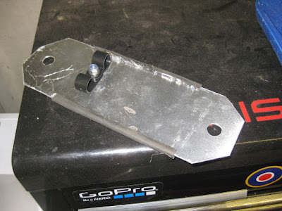
Getting them past the handbrake mechanism taxed me a little, I didn't want the cables anywhere near the moving mechanical parts at the top of the tunnel, but the sides are occupied by the fuel lines one side & the brake lines the other. In the end I made a plate to fit between the seat mounting bolts, bridging the tunnel & mounted the cables to the upper side of that. Further forward the tunnel is deeper & there's more options.

 I put another terminal on the earth wire (plastic cars need an earth line) & fitted a riv-nut to bolt it to the engine cradle just inside the engine bay, the live I've left dangling until the engine is in. All that took a day as I didn't want to trust pop-rivet so had to remove most of the interior to fit bolts to attach the P-clips - a proper faff, but worth it.

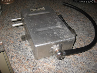
Today I turned my attention to the fuel system, starting by de-rusting & treating the fuel tank (also the rear axle tube & the rear trailing arms while I was there). I've just about positioned the high & low pressure fuel pumps on the fuel system plate, but I'm waiting for a few more bits to arrive in the post before I commit holes. I did open up the drain hole in the bottom of an old oil catch tank to M10 & fitted a banjo bolt because the tank will be the fuel swirl pot & the banjo fitting will be the air route back to the tank. There are of course lots of shiny swirl pots available, but unless you have a particular polished aluminium fetish they are without exception a waste of money, all you need to do is slow down the flow of the fuel so the the air can rise to the top, then vent that back to the tank. Almost any fuel-tight container will do - on the Rickman I used an old fuel filter from a scrapped Sierra, this is the second time I've used an old catch tank. Swirl pots are FREE.

Another thing to get attended to was the handbrake, The guy I bought the car from said he'd changed the handbrake cable & indeed it looks new, however, it feels awful, it's notchy & it doesn't pull the brakes on - at all - my drive really doesn't slope much, but the car will roll down it with the handbrake on. Looking underneath It's the usual kit car thing of not holding the cable outer in line with the cable run, so it twists & snags the cable inner. I simply made up an aluminium channel with a P-clips at each end to hold the cable outers togethr about an inch away from the mounting plate, now the outers have to stay aligned, the inners don't get trapped. Then I made a strap to hold the near side cable outer up, the offside one will be clipped to the fuel plate.

Little by little the car comes together.

Wednesday 25 November 2020

Latest

 The following day was not so lucky. I spent the whole morning trying to take the fuel tank out - failed. I did succeed in replacing a couple of very rusty spacers with plastic ones. The chassis paint was oll dry - still on my hands 3 three later, after that I did some investigating & also made a brace for the handbrake that stops it being pulled to one side & binding up the cable, maybe the brake will now be capable of holding the car on a gentle gradient - which would bee nice - but as the cars a foot in the air with all the wheels dangling, I'm unlikely to find out any time soon.

While I was under the car I made up a fuel plate to carry the low pressure pump, swirl pot & high pressure pump. Hopefully the high pressure filter as well if there's space. It's made from an aluminium box lid I liberated from a scrap bin some time ago.


Since then I've been mostly spending money, many many small items are on thier way to me - the first of which - the battery cable, arrived today. As I sit here I've drawn up a fairlead to take it through the boot wall into the space under the car to run forward the the engine bay, so as soon as the 3D printer's finished a re-print of something I posted to someone but it never arrived, I'll pint the fairlead (two halves) & hopefully the terminals will arrive tomorrow & I can get that finished. Also on it's way is a very expensive plenum for the inlet side of the engine.

Saturday 21 November 2020

Lucky Day

 I wandered Out to the garage this morning with no real plan. I decided I'd look at putting the Fiesta battery tray in the boot - I'd already removed it from the brackets on the subframe. It had two captive bolts with splines under the heads - which I knocked out - but I'd need bolts for the other end, something low profile so it didn't push into the battery, something that would lock into the tray so I could do up the nuts from the outside. Obviously impossible - and yet - the first thing I saw on a shelf was two mushroom head, galvanised bolts with a square under the head, I'd drilled the boot floor so now I enlarged the holes in the tray to 7mm & used a nut to press fit the square into the round hole - perfect, but I'd need a battery clamp.

A little while ago I took apart a shelf unit thing & put a couple of 8mm ish rods with threaded ends in the metal store, I took one out, cut it in half & bent the cut end into a hook to fit in the hole in the battery tray, I made a strap for the top, but when I tied a nut on, the threads were not M8. No problem, I'll take one to Margnor, they may even have wing nuts. I moved on to another little problem - the Zetec flywheel had no clutch dowels. I established they needed to be 1/4" & thought about an old toolbox with stuff left ofer from my first car build - about 40 years ago. The car was imperial so I've kept the nuts & bolts separate, in seconds I'd found a disc brake pad retaining pin exactly the right size, in a few more seconds I'd found TWO WING NUTS that fit on the battery clamp threads, then the phone beeped to say my new angle grinder had arrived!!

So, the battery is now all moved & clamped down & after picking up the angry grinder I was able to cut off the old battery brackets smooth down the welding & paint the front subframe with POR-15 to kill the rust & act as a base coat for the final colour. I've also fitted riv-nuts in the subframe for the inner wings,

I took the clutch off the old engine, the clutch cover looks fine, but the friction plate is quite worn, so I need to get a new one on order before the engine can go onto the gearbox & get re-fitted to the car.

That makes it sound as iff the job's almost done but there's lots of systems type jobs still to do:-

Run battery leads to the front of the car.

Convert the fuel system to high pressure.

Take the dash out & fit the ECU & a few relays.

Get an intake plenum & modify it to fit.

Run the engine bay wiring.

Work out which exhaust manifold I'm going to use & make it fit.

Get & fit the crank, cam & lambda sensors.

There are no mjor unknowns there, so I'm hoping to just keep working steadily towards it & make it work.

A first start in February would be good.

Thursday 19 November 2020

Angle Grinder All Used Up

 Acouple of weeks ago the angle grinder started getting unreliable. I looked at the brushes & they were worn down to the last couple of mm, so I ordered a new pair. Yesterday the speed started wavering so I looked at the brushes & the new ones were a coulple of mm long. I guess the armature has worn away then. New angry grinder on order. I shalln't do an un-boxing video.

Why has the angry grinder worn out? Well I've about finished the welding of the front sub-frame & even carried out a static test by lifting the front of the car with it.

I've also mostly taken off the black powder coat (with a wire bruch in the angle grinder) & cleaned the oil off the front bulkhead (see it's gleaming whiteness!), so now I need to apply some sealant to the holes in the sub-frame & then paint with anti-corrosion paint & then top coat. Pale grey I think. A lot of people insist that black is the only colour for a chassis, but it makes it so much harder to see cracks & that little screw you dropped into the depths of the engine bay.

Also on the jobs list for today was a good wire brushing & a coat of paint on the engine block. Usually I go for red, but on this car it's blue. The cam box may well get the red stripped & left natural alloy. There's a few ancillary parts that will need a coat of black when I next have a pot open.

In a bizarre twist of fate, the engine & gearbox from the Fury appeared in a FaceAche ad today, I don't have an account, but one of the chaps on the SKCC forum saw it & posted a link. I wonder if the next owner will like - or even use - the throttle linkage & sweated over?

Sunday 15 November 2020

And There's More.....

 Having welded the upper tube in whthout setting fire to anything, I se about the lower tube. This one does have some structural significance as the drag links from the front suspension connect to the front of it. Gete it wrong & the car will have more castor one side than the other, get it BADLY wrong & the front subframe will crumple under braking. Best think about this then.


The instructions I'd seen said cut out the 40 x 40 tube & replace it with two stacked & welded 25 x 25 tubes. In the end, I cut the 40 x 40 tube down into a 25 x 25 angle, flared out to 40 x 40 at each end, then cut the stacked & welded 25 x 25 tubes so the nestled into it. I managed to get the cut pretty good, less than a mm gap all the way along & nicely cut around the other tubes at the end.


This was obvously a LOT more work, but has significant advantages:-

1/ the remains of the original tube is probably strong enough

2/ most or the original weldng is retained.

3/ the drag ling mounting is untouched.

4/ the brake pipe mounting is untouched

5/ the holes for mounting the inner wing are still in place.

^^ This is a view from inside the enging bay showing the new double tube in place inside the remains of the old tube, you can see how it swellsat either end to keep the original welding

In fact the only thing my new fabricatio is doing is stabilising the angle which makes me comfortable.

>> This is a view from outside & behind showing the new tube let into the original structure.

There's more welding to do as this way of doing it needs welding at both ends and along two sides, but it should be stronger & less reliant on the quality of my weling - though I was pleasantly surprised when I cut the pre-welded double tube to length, my welding had proper penetration & everything.

So a little more welding & a little more grinding, some paint & the new engine can go in.

Gosh!

Cutting & Shutting

 Yesterday I took a brave pill & cut out the upper tube. I supported the car at the front bulkhead & carefully supported the bonnet mounts so the subframe didn't sag.


------->  Before


------>  After


This tube wasn't much of a worry because it does little more than stabilise the radiator frame & provide a little crash protection.


The welding went OK (mostly) & when it looked proper & hitting it with a hammer resulted in a ring rather than a thud, I stood back & decided I'd pushed my luck far enough for on day.


But I wasn't finished yet - moving on to things I felt more comfortable with, I cut a hole in the bulkhead for the ECU plug. This was easier than expected - the firewall is about 10mm thick here, two skins with a filler between & the hole needed to be 80mm diameter. I chain-drilled it & dremelled it to size thinking the grommet wouldn't fit over a panel that thick, but on looking at it, it's made for a panel about 8mm, so it fitted beautifuuly - RESULT!

 The ECU will go nicely up behind the glove box & the OBD port - yes, an OBD port! - will probably sit in a hole in the glovebox wall.


Friday 13 November 2020

A Little Lift

It was always obvious that the engine wasn't coming out the conventional way, the pulleys are hard against the subframe rails, so it would have to come out with the gearbox. That meant it was easier to take the car off the engine / gearbox / front suspension.

I'd already stiffenned a garage roof beam & decided the car weighed 750kg, mostly at the front, so the weight to be left on the floor (engine etc) was about 250ish kg, leaving 500 kg biased towards the back. The hoist has a limit of 250kg, so - easy then.

I removed all the M10 bolts holding the Ford parts to the sub-frame & realised - with not a little disappointment - that there were no crush tubes in the cross member so when the M10 bolts had be tightnned, the tubes had crushed.

The photo is of the worst one & it's not too bad, but when you see the quality of the engineering in the composite parts of the car, I was expecting better than this.

Anyway, I left work early & visited Margnor & bought a selection of shiny things, among them were some beefy square washers to put over the sunken areas & spread the load out to the side walls of the tube.


All of that is way in the future though. I disconnected the front track arms, steering links, brake lines, gear shift & strut top mounts, so the front of the car was just resting on the suspension. 

I'd already put an engine "skate" under the engine & gearbox, so I wrapped a chain round the lower cross tube, hooked that onto the electric hoist & pushed the button.

The car rose, I took it up in small amounts as the higher it got, the more weight is on the back wheels, then when it looked properly scary I was able to wheel the engine skate out from under the
car & roll the car back a little to give me some space to work on the engine.


I've now dropped the car down onto axle stands so I can clean & paint the front subframe, it's not badly rusted but after the new sections are welded in, I shall wire brush it & re-teat it all before the new engine goes in.

The new engine also needs a coat of paint & probably a cam belt, but hopefully it won't be too long before they're getting mated back together.

Then the hard work starts with the engine bay wiring & locating equipment. I think I may be able to re-locate the battery to the boot to free up some space under the bonnet. There's plenty of room in the boot, basically the whole rear half of the car is storage.


Wednesday 11 November 2020

Stripping

 Last weekend I girded my loins & set to taking the Quantum apart. As usual the engine started up straight away so I could square it up in the garage - I just hope it's as reliable when all this is over.

I took all the ancillaries off & put some parts through my new parts washer ready for paint. It's pretty obvious the engine isn't going to come off the gearbox because the sub-fame's in the way, so the plan is to lift the car off the engine / gearbox / front suspension.

On the dissapointing side, the gearshift isn't going to be easy to improve. It seems that on the early gearboxes the stick "feel" that sort of guides the gearstick into the gates was done at the gear change, on the later cars that was all done in the gearbox. Unfortunatly I have an early gearbox with no "feel" & a late gear change - with no "feel" which is why the gearstick feels like it's not attached to anything.


 I spent an hour carefully re-shaping the birds nest of brake lines outboard of the brake servo to a/ make them look better & not rub against each other & b/ so I could fit a swirl pot in the space I'd created. Then I decided to put a fuel plate for the pumps & filters under the back seat where there's plenty of space. I'm sure there's something else I can put next to the servo.


Tuesday 20 October 2020

Farcester

With foul weather promised for the weekend it looks like the CVH Quantum has travelled it's last - long live the Zetec Quantum!

Things have begun slowly, but they have begun. The two new sub-frame rails have been made & the engine mounting has been modified to fit the engine. I need to get some M10 bolts, but that's a small matter & will pop over to Margnor probably on Friday.

My welding is getting better - helped by the steel being at least 2mm think.

The plan I followed suggested putting a single gusset across the bend in the tube, but if there were to be any flex in the joint, the gusset would be pushing on the flat metal between the corners & would do little to prevent the flexing, so I cut & shaped an off-cut of the 1" box tube so each horizontal web is supported directly, it's not a huge amount stronger, but it is less susceptable to fatigue. It's over-length at the moment, it'll get trimmed to suit when the old one is cut out.


The engine mount is cut, welded, cleaned up & painted ready to get bolted on as soon as I get some bolts.